
-

-

-

- Austria (27)
- General (16)
- HowTo (122)
- IT Security (129)
- Linux (128)
- Networking (65)
- Other (4)
-

- CDemu - a free, gpl cd/dvd-rom device emulator for linux
- heatpumpMonitor - Monitoring a Stiebel Eltron LWZ
- ignis backup tool - the heat-strengthened backup tool
-

- May 2026 (1)
- December 2021 (2)
- September 2019 (1)
- May 2019 (1)
- April 2019 (1)
- January 2019 (1)
- October 2018 (1)
- August 2018 (1)
- February 2018 (1)
- September 2017 (1)
- August 2017 (2)
- May 2017 (1)
- April 2017 (1)
- February 2017 (1)
- January 2017 (2)
- December 2016 (1)
- November 2016 (2)
- October 2016 (1)
- September 2016 (1)
- August 2016 (1)
- July 2016 (2)
- April 2016 (1)
- March 2016 (3)
- February 2016 (4)
- January 2016 (2)
- December 2015 (2)
- November 2015 (2)
- September 2015 (2)
- July 2015 (5)
- June 2015 (4)
- May 2015 (2)
- February 2015 (1)
- January 2015 (4)
- December 2014 (1)
- November 2014 (5)
- October 2014 (4)
- September 2014 (1)
- August 2014 (4)
- July 2014 (3)
- June 2014 (5)
- May 2014 (5)
- April 2014 (1)
- March 2014 (2)
- February 2014 (3)
- January 2014 (5)
- December 2013 (2)
- November 2013 (3)
- September 2013 (3)
- August 2013 (2)
- May 2013 (4)
- April 2013 (1)
- March 2013 (1)
- February 2013 (3)
- December 2012 (3)
- November 2012 (3)
- October 2012 (1)
- September 2012 (2)
- June 2012 (1)
- May 2012 (1)
- April 2012 (1)
- March 2012 (1)
- February 2012 (1)
- January 2012 (1)
- December 2011 (4)
- November 2011 (1)
- August 2011 (1)
- March 2011 (1)
- October 2010 (1)
- May 2010 (3)
- January 2010 (1)
- September 2009 (1)
- August 2009 (5)
- July 2009 (5)
- June 2009 (4)
- May 2009 (1)
- April 2009 (1)
- January 2009 (1)
- December 2008 (6)
- November 2008 (6)
- October 2008 (2)
- September 2008 (11)
- August 2008 (4)
- July 2008 (7)
- June 2008 (2)
- May 2008 (7)
- April 2008 (5)
- March 2008 (9)
- February 2008 (15)
- January 2008 (11)
- December 2007 (3)
Howto setup a redundant and secure BGP (full table) Internet connection with Mikrotik Routers
March 22, 2014
Looking through the Internet, there are much howto’s specially in the OpenSource field but a guide line for a redundant and secure internet connection based on BGP (full table) is not something you find on many sites. So I thought I write such a documentation and I’m hoping it helps some networks admins in setting up their company internet connection. BGP is not that hard ;-).
General conditions
Following points are the general conditions for this howto:
- Two Internet Uplinks to two different providers, each connected via one fibre link
- One provides the BGP peer in the same VLAN and one peer is only reachable via a routing hop (to show the different configuration)
- One provider hands the customer only one peering IP address and the other two (to show the different configuration)
- We use 2 BGP routers on our side for redundancy
- Both provide IPv4 and IPv6 Full Tables
- No traffic engineering to steer traffic to one provider over the other is done
- A failure of
- one router must not change anything for the user/customer
- one switch is allowed to lose one Uplink but not both, so traffic for the user/customers needs to be unaffected
- one fibre link leads to one Uplink down, but the traffic for the user/customers needs to be unaffected
- Secure setup
- Setting up the layer 2 switches and the redundant firewall behind the routers is not part of this howto
- Using Mikrotik RouterOS devices as the routers in the config part, but the same setup would also work with Cisco or Vayatta routers, which I’ve also used for BGP based Internet connections.
Setup
Following drawing shows the setup for the BGP Internet connection.
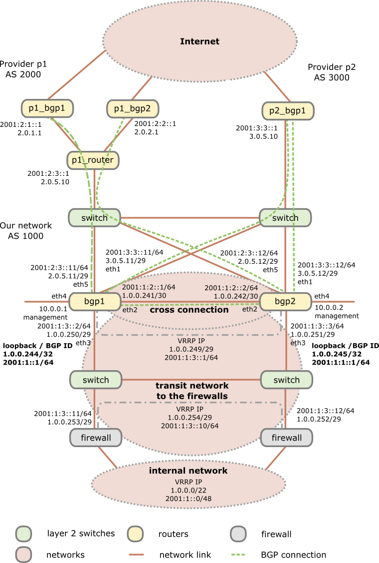
As you see I’m using 2 switches as media converters and to distribute the provider transit networks to both routers. Why I do this as there are Mikrotik routers with SPF and SPF+ modules? First using a Mikrotik on a x86 provides you with no switching (just bridging). Secondly even if you use a Mikrotik Hardware router with switching support, a switch that is only used for layer 2 stuff and has no IP interface in the public networks (only in the management network) will be more stable specially concerning firmware updates than routers which are used for active interaction with other systems. No update for multiple years is not uncommon for switches in this scenario, which is not valid for the routers, specially if you use some special features on the routers. This means you can update a router without the Ethernet link to the provider going down and as the Mikrotik boots under 30 seconds its a minimal impact. The default switching time for BGP is 180 seconds (3*60 seconds) which is much longer than a boot after a firmware update.
Configuration of the routers
If not specified the configuration is the same for both routers and the syntax works with RouterOS 6.10, but it does not change that much normally, at least not since version 4 when I started using Mikrotiks.
First we start with the names of the routers
BGP1:
/system identity set name=bgp1
BGP2:
/system identity set name=bgp2
And now to the actual work – we need to configure our interfaces. We create a loopback interface for at least following reasons:
- This interface is always up, so the IP address is always up – good for monitoring the node vs interfaces
- We use the IP address on this interface as our OSFP and BGP ID
- We use it to blackhole routed traffic .. more later in this post
/interface bridge add name=loopback

/interface ethernet

set [ find default-name=ether1 ] name=ether1vlanTransitProvider2

set [ find default-name=ether2 ] name=ether2vlanCrossConnection

set [ find default-name=ether3 ] name=ether3vlanTransitFirewall

set [ find default-name=ether4 ] name=ether4vlanMgmt

set [ find default-name=ether5 ] name=ether5vlanTransitProvider1
As Mikrotik allows to rename the interface we do so as it makes configuration lines which use these interfaces much easier to understand … believe me I’ve routers with > 100 interfaces :-). For the transit network to the firewall we’ll setup a VRRP and to be somewhat more secure than normal VRRP we also set a long and random password. We configure also a no default VRID, as most system use 1 as default and who knows what the firewalls use. 😉
BGP1:
/interface vrrp add interface=ether3vlanTransitFirewall name=vrrpTransitFirewall password=XXXXXXX priority=250 vrid=10
BGP2:
/interface vrrp add interface=ether3vlanTransitFirewall name=vrrpTransitFirewall password=XXXXXXX priority=200 vrid=10
So if the BGP1 is up, it always will be the master. Now we need to configure the IP addresses …. lets start with IPv4
BGP1:
/ip address

add address=1.0.0.244/32 interface=loopback

add address=3.0.5.11/29 interface=ether1vlanTransitProvider2

add address=1.0.0.241/30 interface=ether2vlanCrossConnection

add address=1.0.0.250/29 interface=ether3vlanTransitFirewall

add address=1.0.0.249/29 interface=vrrpTransitFirewall

add address=10.0.0.1/24 interface=ether4vlanMgmt

add address=2.0.5.11/29 interface=ether5vlanTransitProvider1
BGP2:
/ip address

add address=1.0.0.245/32 interface=loopback

add address=3.0.5.12/29 interface=ether1vlanTransitProvider2

add address=1.0.0.242/30 interface=ether2vlanCrossConnection

add address=1.0.0.251/29 interface=ether3vlanTransitFirewall

add address=1.0.0.249/29 interface=vrrpTransitFirewall

add address=10.0.0.2/24 interface=ether4vlanMgmt

add address=2.0.5.12/29 interface=ether5vlanTransitProvider1
And now we do the same for IPv6 … just the internal management is kept IPv4 only, as you don’t need it there normally (at least I’m not)
BGP1:
/ipv6 address

add address=2001:1::1/64 interface=loopback

add address=2001:3:3::11/64 interface=ether1vlanTransitProvider2

add address=2001:1:2::1/64 interface=ether2vlanCrossConnection

add address=2001:1:3::2/64 interface=ether3vlanTransitFirewall

add address=2001:1:3::1/64 interface=vrrpTransitFirewall

add address=2001:2:3::11/64 interface=ether5vlanTransitProvider1
BGP2:
/ipv6 address

add address=2001:1:1::1/64 interface=loopback

add address=2001:3:3::12/64 interface=ether1vlanTransitProvider2

add address=2001:1:2::2/64 interface=ether2vlanCrossConnection

add address=2001:1:3::3/64 interface=ether3vlanTransitFirewall

add address=2001:1:3::2/64 interface=vrrpTransitFirewall

add address=2001:2:3::12/64 interface=ether5vlanTransitProvider1
Now we add our static routes we need. We need to set one for our management network, so we can be reached via the admin computers and set the route for provider 1 as the BGP routers are not in the same subnet. Also the router to the firewalls for our internal network is clear, but we need one more feature which needs some explaining. If the link to the firewalls goes down on a router, the IP address / network also goes down and its routes over this interface. As the router redistributes the connected and static routes via BGP it will not anymore send it out. This is basically ok, but now something comes into play that is called “BGP Route Flap Damping“, which can lead to the problem that everything is running again but some AS are not setting traffic to you for some time. So it is paramount to keep the announcing running as stable as possible, which leads us to black hole routes. As in IPv6 Mikrotik does not support it (as of yet) we use a workaround to accomplish the same. PS: you can use the same to black hole an attacker .. really fast and without much load on the system … just saying 🙂
/ip route

add distance=1 dst-address=10.0.0.0/8 gateway=10.0.0.254

add distance=1 dst-address=2.0.1.1/32 gateway=2.0.5.10

add distance=1 dst-address=2.0.2.1/32 gateway=2.0.5.10

add distance=1 dst-address=1.0.0.0/22 gateway=1.0.0.254

add comment="if interface to firewall goes down, this route is used" distance=254 dst-address=1.0.0.0/22 type=blackhole
/ipv6 route

add distance=1 dst-address=2001:2:1::1/128 gateway=2001:2:3::1

add distance=1 dst-address=2001:2:2::1/128 gateway=2001:628:1400:1003::1

add distance=1 dst-address=2001:1::0/48 gateway=2001:1:3::10
BGP1:
add comment="if interface to firewall goes down, this route is used" distance=254 dst-address=2001:1::0/48 gateway=2001:1::ffff
BGP2:
add comment="if interface to firewall goes down, this route is used" distance=254 dst-address=2001:1::0/48 gateway=2001:1:1::1:ffff
After the IP addresses and static routes are configured we need to secure our setup before doing anything else. As the BGP routers are in front of the firewalls they can get attacked directly from the Internet, sure, but traffic (e.g. attacks, P2P, …) to systems behind it can also make problems for the routers, so we’ll do something that we normally don’t do. We’ll disable connection tracking – we are a plain and stupid router … let the firewall track connections, we don’t care. This takes much work from the router if you’ve many many connections over it. Sure it makes the firewall settings on the router harder but as said, let the router focus on its single task – route traffic as much and as fast as possible. I sometimes see BGP routers overloaded with other tasks and than people complain that they have problems with high loads. If your network/uplinks is so small, that it does not matter, sticking with connection tracking is also ok – you’ll just can change the firewall rules to use connection awareness.
/ip firewall connection tracking set enabled=no

/ip settings set tcp-syncookies=yes
Now we create a address list of our BGP peers which we will allow to connect to our BGP daemon. Don’t forget your routers, as they talk also between themselves:
/ip firewall address-list

add address=2.0.1.1 list=listBgpIPv4Peers

add address=2.0.2.1 list=listBgpIPv4Peers

add address=3.0.5.10 list=listBgpIPv4Peers

add address=1.0.0.241 list=listBgpIPv4Peers

add address=1.0.0.242 list=listBgpIPv4Peers
/ipv6 firewall address-list

add address=2001:2:1::1 list=listBgpIPv6Peers

add address=2001:2:2::1 list=listBgpIPv6Peers

add address=2001:3:3::1 list=listBgpIPv6Peers

add address=2001:1:2::1 list=listBgpIPv6Peers

add address=2001:1:2::2 list=listBgpIPv6Peers
And now to actual firewall rules:
/ip firewall filter

add chain=input comment="BGP incomming is ok on all interfaces from our peers" src-address-list=listBgpIPv4Peers dst-port=179 protocol=tcp

add chain=input comment="without conntrack we need to allow that" dst-port=1024-65535 protocol=tcp src-address-list=listBgpIPv4Peers

add chain=input comment="OSFP is on the crosslink ok" in-interface=ether2vlanCrossConnection protocol=ospf

add chain=input comment="VRRP is ok on the interface to the firewalls" dst-address=224.0.0.18 in-interface=ether3vlanTransitFirewall protocol=vrrp

add chain=input comment="everyone can ping us" protocol=icmp

add action=drop chain=input comment="we drop any request from not from the Mgmt Interface" in-interface=!ether4vlanMgmt
/ipv6 firewall filter

add chain=input comment="BGP incomming is ok on all interfaces from our peers" src-address-list=listBgpIPv4Peers dst-port=179 protocol=tcp

add chain=input comment="without conntrack we need to allow that" dst-port=1024-65535 protocol=tcp src-address-list=listBgpIPv6Peers

add chain=input comment="OSFP is on the crosslink ok" in-interface=ether2vlanCrossConnection protocol=ospf

add chain=input comment="VRRP is ok on the interface to the switches" dst-address=ff02::12/128 in-interface=ether3vlanTransitFirewall protocol=vrrp

add chain=input comment="everyone can ping us" protocol=icmpv6

add action=drop chain=input comment="we drop any request from not from the Mgmt Interface" in-interface=!ether4vlanMgmt
Looks like a secure setup .. hopefully it also is :-). Now we’re ready to configure the BGP part, starting with the configuration of the instance.
BGP1:
/routing bgp instance set default as=1000 redistribute-connected=yes redistribute-ospf=yes redistribute-static=yes router-id=1.0.0.244
BGP2:
/routing bgp instance set default as=1000 redistribute-connected=yes redistribute-ospf=yes redistribute-static=yes router-id=1.0.0.245
Now we need to set our networks to announce:
/routing bgp network

add network=1.0.0.0/22

add network=2001:1::0/48
And now we configure our peers. For the 2 BGP routers which are reachable only via an other router we need to set multihop to yes. We need also to make a link between our 2 routers if one sees a peer the other does not but he still is the the VRRP master.
/routing bgp peer
BGP1:
add in-filter=filterIpv4AS2000in multihop=yes name=p1_bgp1 out-filter=filterIpv4GLOBALout remote-address=2.0.1.1 remote-as=2000 tcp-md5-key=xxxxxxxx

add in-filter=filterIpv4AS3000in name=p2_bgp1 out-filter=filterIpv4GLOBALout remote-address=3.0.5.10 remote-as=3000 tcp-md5-key=xxxxxxx

add address-families=ipv6 in-filter=filterIpv6AS2000in multihop=yes name=p1_bgp1 out-filter=filterIpv6GLOBALout remote-address=2001:2:1::1 remote-as=2000 tcp-md5-key=xxxxxxx

add address-families=ipv6 in-filter=filterIpv6AS3000in name=p2_bgp1 out-filter=filterIpv6GLOBALout remote-address=2001:3:3::1 remote-as=3000 tcp-md5-key=xxxxxxx

add name=bgp2 remote-address=1.0.0.242 remote-as=1000

add name=bgp2ipv6 remote-address=2001:1:2::2 remote-as=1000
BGP2:
add in-filter=filterIpv4AS2000in multihop=yes name=p1_bgp2 out-filter=filterIpv4GLOBALout remote-address=2.0.2.1 remote-as=2000 tcp-md5-key=xxxxxxxx

add in-filter=filterIpv4AS3000in name=p2_bgp1 out-filter=filterIpv4GLOBALout remote-address=3.0.5.10 remote-as=3000 tcp-md5-key=xxxxxxx

add address-families=ipv6 in-filter=filterIpv6AS2000in multihop=yes name=p1_bgp2 out-filter=filterIpv6GLOBALout remote-address=2001:2:2::1 remote-as=2000 tcp-md5-key=xxxxx

add address-families=ipv6 in-filter=filterIpv6AS3000in name=p2_bgp1 out-filter=filterIpv6GLOBALout remote-address=2001:3:3::1 remote-as=3000 tcp-md5-key=xxxxxxx

add name=bgp1 remote-address=1.0.0.241 remote-as=1000

add name=bgp1ipv6 remote-address=2001:1:2::1 remote-as=1000
That was not that hard, but what are all this filter names? As I told you in the beginning we’re paranoid so we don’t trust anyone so we’re filtering all routes going in and out. So lets start with the out filters as they are much easier. They just let us announce our own networks, so we won’t account networks of the one provider to the other and therefore make a link for them over us.
/routing filter

add action=accept chain=filterIpv4GLOBALout prefix=1.0.0.0/22

add action=discard chain=filterIpv4GLOBALout
add action=accept chain=filterIpv6GLOBALout prefix=2001:1::0/48

add action=discard chain=filterIpv6GLOBALout
The in filters are at little bit more complicated, but not that hard. We make sure that every AS path we get from the provider starts with his AS. It had happened that some provider are a little bit messy there.
add action=jump chain=filterIpv4AS2000in jump-target=filterIpv4Nomartians

add action=accept bgp-as-path="^2000(,[0-9]+)*\$" chain=filterIpv4AS2000in

add action=accept chain=filterIpv4AS2000in
add action=jump chain=filterIpv4AS3000in jump-target=filterIpv4Nomartians

add action=accept bgp-as-path="^3000(,[0-9]+)*\$" chain=filterIpv4AS3000in

add action=accept chain=filterIpv4AS3000in
add action=jump chain=filterIpv6AS2000in jump-target=filterIpv6Nomartians

add action=accept bgp-as-path="^2000(,[0-9]+)*\$" chain=filterIpv6AS2000in

add action=accept chain=filterIpv6AS2000in
add action=jump chain=filterIpv6AS3000in jump-target=filterIpv6Nomartians

add action=accept bgp-as-path="^3000(,[0-9]+)*\$" chain=filterIpv6AS3000in

add action=accept chain=filterIpv6AS3000in
After this is clear, I only need to explain the reason for the filterIpv4Nomartians and filterIpv6Nomartians filters. Its quite easy, these lists contain IP subnets that we should not get via BGP, because they are not used on the Internet (at least not by good people) so we’ll filter them.
add action=discard chain=filterIpv4Nomartians prefix=0.0.0.0/8

add action=discard chain=filterIpv4Nomartians prefix=127.0.0.0/8

add action=discard chain=filterIpv4Nomartians prefix=192.0.2.0/24

add action=discard chain=filterIpv4Nomartians prefix=10.0.0.0/8

add action=discard chain=filterIpv4Nomartians prefix=172.16.0.0/12

add action=discard chain=filterIpv4Nomartians prefix=192.168.0.0/16

add action=discard chain=filterIpv4Nomartians prefix=192.168.0.0/15

add action=discard chain=filterIpv4Nomartians prefix=168.254.0.0/16

add action=discard chain=filterIpv4Nomartians prefix=240.0.0.0/4

add action=return chain=filterIpv4Nomartians
add action=discard chain=filterIpv6Nomartians prefix=::/96

add action=discard chain=filterIpv6Nomartians prefix=::/128

add action=discard chain=filterIpv6Nomartians prefix=::1/128

add action=discard chain=filterIpv6Nomartians prefix=::ffff:0.0.0.0/96

add action=discard chain=filterIpv6Nomartians prefix=::224.0.0.0/100

add action=discard chain=filterIpv6Nomartians prefix=::/104

add action=discard chain=filterIpv6Nomartians prefix=::255.0.0.0/104

add action=discard chain=filterIpv6Nomartians prefix=::/8

add action=discard chain=filterIpv6Nomartians prefix=200::/7

add action=discard chain=filterIpv6Nomartians prefix=3ffe::/16

add action=discard chain=filterIpv6Nomartians prefix=2001:db8::/32

add action=discard chain=filterIpv6Nomartians prefix=2002:e000::/20

add action=discard chain=filterIpv6Nomartians prefix=2002:7f00::/24

add action=discard chain=filterIpv6Nomartians prefix=2002::/24

add action=discard chain=filterIpv6Nomartians prefix=2002:ff00::/24

add action=discard chain=filterIpv6Nomartians prefix=2002:a00::/24

add action=discard chain=filterIpv6Nomartians prefix=2002:ac10::/28

add action=discard chain=filterIpv6Nomartians prefix=2002:c0a8::/32

add action=discard chain=filterIpv6Nomartians prefix=fc00::/7

add action=discard chain=filterIpv6Nomartians prefix=fe80::/10

add action=discard chain=filterIpv6Nomartians prefix=fec0::/10

add action=discard chain=filterIpv6Nomartians prefix=ff00::/8

add action=return chain=filterIpv6Nomartians
Now we’re done with the BGP setup, only some OSFP stuff is left open. Why OSFP? We want to reach our loopback interfaces via the other router, as only one can be the VRRP master. BGP will only redistribute our complete network and the networks from the provides between our 2 routers, but not some parts of our networks – for this we need OSFP.
BGP1:
/routing ospf instance set [ find default=yes ] redistribute-connected=as-type-2 redistribute-static=as-type-2 router-id=1.0.0.244

/routing ospf-v3 instance set [ find default=yes ] redistribute-connected=as-type-2 redistribute-static=as-type-2 router-id=1.0.0.244
BGP2:
/routing ospf instance set [ find default=yes ] redistribute-connected=as-type-2 redistribute-static=as-type-2 router-id=1.0.0.245

/routing ospf-v3 instance set [ find default=yes ] redistribute-connected=as-type-2 redistribute-static=as-type-2 router-id=1.0.0.245
If you wonder why we use an IPv4 address for the OSFPv3, its because even if its an IPv6 protocol no IPv6 address can be used there … its more like an ID field. Now we only need to set our interfaces and network (only for IPv4 needed):
/routing ospf interface

add interface=loopback network-type=point-to-point passive=yes

add interface=ether3vlanTransitFirewall network-type=point-to-point

add interface=ether2vlanCrossConnection network-type=point-to-point

/routing ospf network

add area=backbone network=1.0.0.240/30

add area=backbone network=1.0.0.248/29

/routing ospf-v3 interface

add area=backbone interface=loopback network-type=point-to-point passive=yes

add area=backbone interface=ether3vlanTransitFirewall network-type=point-to-point

add area=backbone interface=ether2vlanCrossConnection network-type=point-to-point
Basically we’re done …. just some standard setups I’m setting on any Mikrotik and recommend you to set it also:
Change the SNMP Community to something long and not guessable:
/snmp

set contact="Robert Penz" enabled=yes location="datacenter" trap-community=xxxxxxxx trap-generators=interfaces trap-target=10.x.x.x trap-version=2

/snmp community set [ find default=yes ] name=XXXXXXXXXX
Set the clock to the correct timezone and set a NTP server as otherwise the log entries are hard to read:
/system clock set time-zone-name=Europe/Vienna

/system ntp client set enabled=yes mode=unicast primary-ntp=10.x.x.x secondary-ntp=10.x.x.x
Configure a syslog server to have some logs if a Mikrotik booted:
/system logging

add action=remote topics=info

add action=remote topics=error

add action=remote topics=warning

add action=remote topics=critical

/system logging action set 3 bsd-syslog=yes remote=10.x.x.x src-address=<ip of the mikrotik ether4vlanMgmt>
Setting the internal DNS Servers is also a good idea:
/ip dns set servers=10.x.x.x,10.x.x.x
Disable some Services on the Mikrotiks we don’t need:
/ip service

set telnet address=0.0.0.0/0 disabled=yes

set ftp address=0.0.0.0/0 disabled=yes

set www address=0.0.0.0/0 disabled=yes

set winbox address=0.0.0.0/0 disabled=yes
And at last we send traffic samples to our SFlow server …. I would recommend you to have also a good SFlow server for your BGP routers.
/ip traffic-flow target add address=10.x.x.x:9996 version=9
Now you could test your routers, but one last thing I recommend you to install on your router is following script written by MarkB. With one command you get something that looks like show ip bgp summary on Cisco or Vayatta and that makes looking at the BGP stuff much easier on a Mikrotik. Get the script from here.
Any questions or improvement ideas on this setup/howto?
Configure a Synology NAS as OpenVPN client with certificate authentication (and make it stable)
March 8, 2014
Normally I use standard Linux distributions as NAS systems, but in this case it had to be a real NAS (size and price was more important than performance) and it was not at my place –> so I chose a Synology DS214se. But I still needed to setup a certificate based OpenVPN where the NAS was the client and it needed to stay connected all the time. First I though that must be easily done in the GUI as OpenVPN is easy for stuff like this … but I was wrong. First it is not possible to configure a certificate based authentication for OpenVPN in the Synology GUI and secondly if the connection got disconnected it stayed that way. But with some magic it was easily fixed:
Configure Certificate based authentication
First go to the VPN window in Control Panel and configure what is possible via the GUI. e.g. the CA certificate or the server IP address or DNS name. Use anything as username/password:
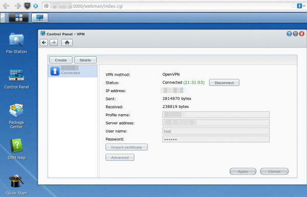
After that save it .. but don’t connect as it won’t work. You need to log in via ssh (use username root and the admin user password) and change some files and upload some new.
cd /usr/syno/etc/synovpnclient/openvpn

ll
will give you something like this
drwxr-xr-x    3 root     root          4096 Feb 23 20:21 .

drwxr-xr-x    7 root     root          4096 Mar  7 21:15 ..

-rwxr-xr-x    1 root     root          1147 Feb 22 18:10 ca_234324321146.crt

-rw-r--r--    1 root     root           524 Mar  2 09:24 client_234324321146

-rw-------    1 root     root           425 Feb 22 18:10 ovpn_234324321146.conf
the file without extension is the configuration for OpenVPN, which gets created from the GUI. The GUI config is stored in the .conf file. So if we change the OpenVPN configuration file it gets overwritten if we change the GUI config, but we won’t do that anymore ;-). Now we create a sub directory and upload our client (=NAS) certificate files. The long and hopefully good documentation on creating the certificates and how to configure OpenVPN on a standard distribution can be found here.
mkdir keys

cat > keys/my_ds.crt    (paste the certificate content and press CRTL-D in an empty line)

cat > keys/my_ds.key  (paste the private key content and press CRTL-D in an empty line)

chmod 600 keys/my_ds.key
Now we change the file without extension so that it contains at leased following lines (other stuff is also required but depends on your setup)
ca ca_234324321146.crt

cert keys/my_ds.crt

key keys/my_ds.key

keepalive 10 120

tls-client
I recommend to make a copy of the file after very change so if someone changes something in the GUI you don’t need to start from the beginning.
cat client_234324321146 client_234324321146.backup
For simple testing start OpenVPN like this (stop it with CTRL-C):
/usr/sbin/openvpn --daemon --cd /usr/syno/etc/synovpnclient/openvpn --config client_234324321146 --writepid /var/run/ovpn_client.pid
And tune it until it works correctly. Now you can start it in the GUI and you’re finished with the first task.
Configure OpenVPN in a way that it keeps running
For this we write a script that gets called every five minutes to check if the OpenVPN is still working and if not restart its.
cat > /root/checkAndReconnectOpenVPN
if echo `ifconfig tun0` | grep -q "00-00-00-00-00-00-00-00-00-00-00-00-00-00-00-00"

then

echo "VPN up"

else

echo 1 > /usr/syno/etc/synovpnclient/vpnc_connecting

synovpnc reconnect --protocol=openvpn --name=XXXXXX

fi

exit 0
Replace XXXXXX with the name the VPN Connection has in the GUI (not sure if it is case sensitive or not, I kept the case anyway.) and make the script executable:
chmod +x /root/checkAndReconnectOpenVPN
Try it with (e.g. when the OpenVPN is running and not running)
/root/checkAndReconnectOpenVPN
Now we only need to add a line to the crontab file (Important it is >> and not >)
cat >> /etc/crontab
and paste and press CRTL-D in an empty line
*/5 * * * * root /root/checkAndReconnectOpenVPN
Now we only need to restart the cron daemon with following commands:
/usr/syno/etc/rc.d/S04crond.sh stop

/usr/syno/etc/rc.d/S04crond.sh start
and we’re finished … a certificate based OpenVPN which reconnects also if the process fails/stops.
Howto capture traffic from a Mikrotik router on Linux
February 15, 2014
If you as I need to get some traffic from a Mikrotik router and /tool sniffer quick doesn’t cut it, as you need not just the headers the best way is stream the traffic to the a Linux box. The Mikrotik configuration is easy, just set the server you want to stream to:
/tool sniffer set streaming-enabled=yes streaming-server=<ip_of_the_server>
Configure a filter as you don’t want to stream everything:
/tool sniffer set filter-ip-address=<an_example_filter_ip>
and now you need only to start it with
/tool sniffer start
and check with
/tool sniffer print
if everything is running.
But now comes the part that is not documented that well. Searching through the internet I found some posts/articles on how to use Wireshark for capturing, but that does not work correctly – at least not for me.
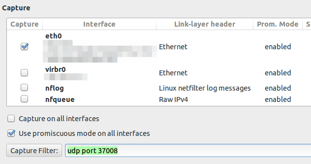
If you configure the capture filter to udp port 37008 to get everything the router sends via TZSP you will see following lines
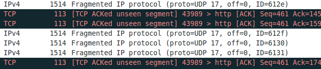
If you now set the display filter to show only TZSP these packets are not displayed any more. This packets contain information we need and I was not able to configure Wireshark 1.10.2 to work correctly. If you know how to get it to work, please write a comment. I changed my approach to use an other program to write the packets to disk and look at them later with Wireshark. And I found a program from Mikrotik directly which does that. Go to the download page and download Trafr and extract and use it like this:
$ tar xzf trafr.tgz

$ ./trafr

usage: trafr <file | -s> [ip_addr]

-s      write output to stdout. pipe it into tcpdump for example:

./trafr -s | /usr/sbin/tcpdump -r -

ip_addr use to filter one source router by ip address

$ ./trafr test.pcap <ip_of_the_router>
After you stopped the program you can open the file in Wireshark and no packets are missing.
Howto find all websites running on a given IP address
January 5, 2014
Sometimes you’ll (at leased if you’re like me 😉 ) want to know which other websites are hosted on the same server respectively the same IP address. The search engine Bing provides a nice feature for this. Just enter ip:50.57.15.204 to get a list of the website which Bing knows to run on that IP address.

But even better, Andrew Horton has done a Bash script which allows you to check that from the command line. This looks even better:
$ ./bing-ip2hosts www.theregister.co.uk

[ 50.57.15.204 | Scraping 11-13 von 13 | Found 9 | / ]]

1695693.r.msn.com

2549779.r.msn.com

forums.channelregister.co.uk

forums.theregister.co.uk

media.theregister.co.uk

m.theregister.co.uk

regmedia.co.uk

www.channelregister.co.uk

www.theregister.co.uk
Howto install Teamviewer 9.x on Ubuntu >= 12.04 64bit (in my case 13.10)
January 2, 2014
Basically it is simple but the 64bit makes it a little bit more difficult. It is not logical from the outside but don’t use the 64bit version. Why? As described here distributions with multiarch support can’t resolve the ia32-libs packages. But there is a simple solution to this which is not described there, as adding an additional architecture doesn’t feel right.
Install gdebi (gdebi lets you install local deb packages resolving and installing its dependencies. apt does the same, but only for remote (http, ftp) located packages.):
sudo apt-get install gdebi
Download the 32bit version
wget http://www.teamviewer.com/download/teamviewer_linux.deb
Use gdebi to install and resolve the dependencies:
$ sudo gdebi teamviewer_linux.deb

Reading package lists... Done

Building dependency tree

Reading state information... Done

Building data structures... Done

Building data structures... Done

Requires the installation of the following packages: libxtst6:i386
TeamViewer (Remote Control Application)

TeamViewer is a remote control application. TeamViewer provides easy, fast and secure remote access to Linux, Windows PCs, and Macs.

.

TeamViewer is free for personal use. You can use TeamViewer completely free of charge to access your private computers or to help your friends with their computer problems.

.

To buy a license for commercial use, please visit http://www.teamviewer.com

Do you want to install the software package? [y/N]:y

Get:1 http://at.archive.ubuntu.com/ubuntu/ saucy/main libxtst6 i386 2:1.2.2-1 [13.8 kB]

Fetched 13.8 kB in 0s (0 B/s)

Selecting previously unselected package libxtst6:i386.

(Reading database ... 250452 files and directories currently installed.)

Unpacking libxtst6:i386 (from .../libxtst6_2%3a1.2.2-1_i386.deb) ...

Setting up libxtst6:i386 (2:1.2.2-1) ...

Processing triggers for libc-bin ...

Selecting previously unselected package teamviewer.

(Reading database ... 250454 files and directories currently installed.)

Unpacking teamviewer (from teamviewer_linux.deb) ...

Setting up teamviewer (9.0.24147) .
Some thoughts on NFS
December 23, 2013
In the last weeks I was working (from time to time 😉 ) on a new setup of my NAS at home. During this I learn some stuff I didn’t know about NFS which I want to share here. I assume that you got the basis NFS stuff working or know how it works and want some addition tips and ticks
- How to query a NFS server for the exported directories and the settings? Easy, use
showmount -e <servername>. Here an example:
$ showmount -e 10.x.x.x

Export list for 10.x.x.x:

/data/home 10.x.x.0/255.255.255.0 - Use fsid – why?
- NFS needs to be able to identify each filesystem that it exports. Normally it will use a UUID for the filesystem (if the filesystem has such a thing) or the device number of the device holding the filesystem (if the filesystem is stored on the device). If you want to an export different file system (e.g. replacement HDD) the fsid changes and you’re clients have to remount (as they have a stale NFS mount). Read more on this topic here.
- Some file systems don’t have a UUID, e.g. encfs does not … use a separate fsid for each export!
- You can export multiple file system with one mount request by the client, if you use nohide. Normally, if a server exports two file systems one of which is mounted on the other, then the client will have to mount both file systems explicitly to get access to them. If it just mounts the parent, it will see an empty directory at the place where the other file system is mounted. That file system is “hidden” – if you don’t want that use nohide, like in this example:
/data/media     10.x.x.0/255.255.255.0(fsid=1,rw,async,no_subtree_check)

/data/media/movies 10.x.x.0/255.255.255.0(fsid=2,rw,async,no_subtree_check,nohide) - If you changed
/etc/exportsyou don’t need to restart your NFS daemon. If the init script provides a reload thats good – if not useexportfs -rav.
So far that are my new learned tips and tricks … I think there was one more but I can’t remember it now. Will add it later if I remember.
Howto restart a suspended KVM guest which can’t be resumed
November 3, 2013
I just had the problem that I was not able to resume a suspended KVM guest. It happened when I powered my KVM server down to add a new hard disk. My server did not power the guest down but did instead suspended them. I realized that only after I did have no “Run” .. just a “Restore” to choose from.
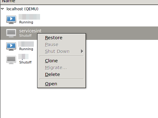
When I tried to “Restore” it I go following:
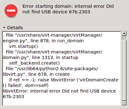
The problem was that I removed a mapped USB device some time ago but at resuming KVM checked for it. The solution was to remove the corrupted suspended virtual machine session so I could boot the machine again – naturally I did lose the suspended session, but that was ok.
[root@kvmserver ~]# virsh managedsave-remove <NameOfGuest>

Removed managedsave image for domain servicesint
Maybe there is a graphical way to do it, but I didn’t look further – as it worked.
Howto get your external IP address via command line
September 28, 2013
I just had to find out the external IP address (as seen from the Internet) of a Linux server which is behind a NAT router. The normal way to goto WhatsMyIP didn’t work as I was only connected via SSH to this server. But the solution is quite easy thanks to the guys from ipecho, just type:
wget http://ipecho.net/plain -O - -q ; echo
Thats so easy! And even faster than using a browser in the first way ….. 🙂
Howto access MTP devices via USB on Ubuntu 12.04
September 1, 2013
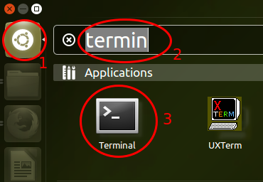
A friend asked me how he can access his Nexus 7 device via USB on his Ubuntu 12.04 notebook. With Android versions below 4.0 that was simple as the device registered as mass storage device. The problem now is the stock Ubuntu 12.04 does not support MTP via GVFS (the virtual filesystem of the GNOME desktop). Newer Ubuntu versions e.g. 13.04 have already a GVFS version which support MTP. But these are no LTS versions of Ubuntu, which I recommend for the average user. But it is quite easy to install a newer version of GVFS on Ubuntu 12.04 (and 12.10) that does support it.
First you need to start a terminal. For this click on the dash home icon (1) and than type “terminal” (2) and you’ll the terminal icon – click on it (3.)
Now copy and paste following into the Terminal (the PC needs to be connected to the Internet while going through these steps):
sudo add-apt-repository ppa:langdalepl/gvfs-mtp
Enter your user password and than you’ll be shown following text:
You are about to add the following PPA to your system:

These builds of gvfs have my native mtp backend backported from gvfs master. Use this to easily access MTP based devices with Nautilus.

More info: https://launchpad.net/~langdalepl/+archive/gvfs-mtp

Press [ENTER] to continue or ctrl-c to cancel adding it
Hit the Enter Key. After this is done you need to type following command, which updates the package list:
sudo apt-get update
After this was successful you need to upgrade the installed packages with:
sudo apt-get upgrade
It should show something like this:
Reading package lists... Done

Building dependency tree

Reading state information... Done

The following packages will be upgraded:

gvfs gvfs:i386 gvfs-backends gvfs-bin gvfs-common gvfs-daemons gvfs-fuse gvfs-libs gvfs-libs:i386 libmtp-common libmtp-runtime libmtp9

12 upgraded, 0 newly installed, 0 to remove and 0 not upgraded.

Need to get 4,193 kB of archives.

After this operation, 4,157 kB of additional disk space will be used.

Do you want to continue [Y/n]?
Just press Enter here (the Y is the default section) to install the packages.
Now you just need to restart your PC and after login just connect your Android device to the PC and the file manager Nautilus will launch with your USB device.
Howto to quick test a DSCP based QoS system?
August 29, 2013
You’ve just completed your QoS system, which is based on DSCP for classifying and managing network traffic? Sure there are many sophisticated methods to validate your configuration, but there is also a really simple one which you can do from every Windows or Linux PC as a first check.
And you won’t believe it – the program is called ping. On Linux use the option -Q to set the DSCP value of the packets. From the manual:
-Q tos Set Quality of Service -related bits in ICMP datagrams. tos can be either decimal or hex number. Traditionally (RFC1349), these have been interpreted as: 0 for reserved (currently being redefined as congestion control), 1-4 for Type of Service and 5-7 for Precedence. Possible settings for Type of Service are: minimal cost: 0x02, reliability: 0x04, throughput: 0x08, low delay: 0x10. Multiple TOS bits should not be set simultaneously. Possible settings for special Precedence range from priority (0x20) to net control (0xe0). You must be root (CAP_NET_ADMIN capability) to use Critical or higher precedence value. You cannot set bit 0x01 (reserved) unless ECN has been enabled in the kernel. In RFC2474, these fields has been redefined as 8-bit Differentiated Services (DS), consisting of: bits 0-1 of separate data (ECN will be used, here), and bits 2-7 of Differentiated Services Codepoint (DSCP).
On Windows the same is achieved with -v
In both cases you need to provide the Type of Service (TOS) byte. While this is not the wished DSCP value, the ToS byte (or 8-bits) encompasses DSCP. DSCP only uses the first 6 bits of the ToS byte and ignores bits 7 and 8. You’re asking ??hey?? 😉
There is a quite easy way to get from one to the other: DSCP * 4 = TOS, or you can use following table.
Most VoIP systems use AF31(DSCP 26) for signaling (e.g. SIP) and EF (DSCP 46) for voice/media (e.g. RTP). This means for testing we use
ping -Q 104 <ip_address> # for DSCP 26

ping -Q 184 <ip_address> # for DSCP 46
After calling these commands you can easily check your counters if the increment correctly. After this put some load on the connection/link e.g. with FTP or SCP and let the ping run, it should be stable and with a low latency. If not the VoIP stuff with also not work. 😉
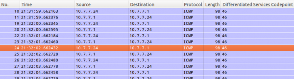
This quick test can also help you by an other problem. You need to deploy a system which relies on the fact that the DSCP value in not being stripped away in transit. For this you use the above command and let Wireshark run.
First you need to add the DSCP colum. Just select a packet and then select the DSCP header and use the right mouse button to get to the “Apply as Column” menu entry.
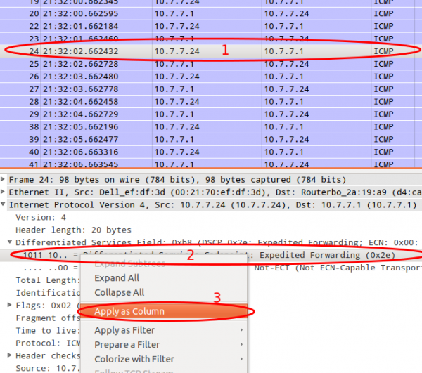
After this you can just look at the DSCP values. If they travel across the network everything is Ok.
Powered by WordPress
Entries and comments feeds.
Valid XHTML and CSS.
53 queries. 0.070 seconds.